CheMaRy Web Page
Electronics, DIY, programming and more…
DIY Power over ethernet (PoE)

At my home the ADSL router and my room are in the opposite sides of the house, the Wifi signal that arrives to my room is so low that I can barely use it on my phone or tablet. I have an Ethernet cable that goes from the router to my room so I decided to place a Wifi access point in the middle.
The problem is that there is no power outlet around, the solution is to send the power over the Ethernet cable (PoE) along with the signal. There are commercial products that do it, but is funny doing it yourself and I have an old WRT54GC wifi router that is perfect for that.
It seems simple, Ethernet at 100Mbips only uses 4 of the 8 wires so you can send the power over the unused wires. But, it was not as easy as I expected, I found some problems:
- The unused wires of the Ethernet cable are internally connected on the router, if you try to connect the power to them directly you are going to blow up the router or the power adaptor.
- The cable was so long that it has a considerable resistance, I can only get a fraction of the input voltage on the other side of the wire (the voltage drop out is worse when you need a low voltage and high intensity like my wifi router that works at 3.3V, maybe if it had worked at 12V I wouldn’t have had this problem).
To solve these problems I made two circuits, the first was a simple mixer that feeds the power an the Ethernet signal into one Ethernet cable, on the other end other circuit splits them again and converts the voltage that is higher that the needed to the required 3.3V.
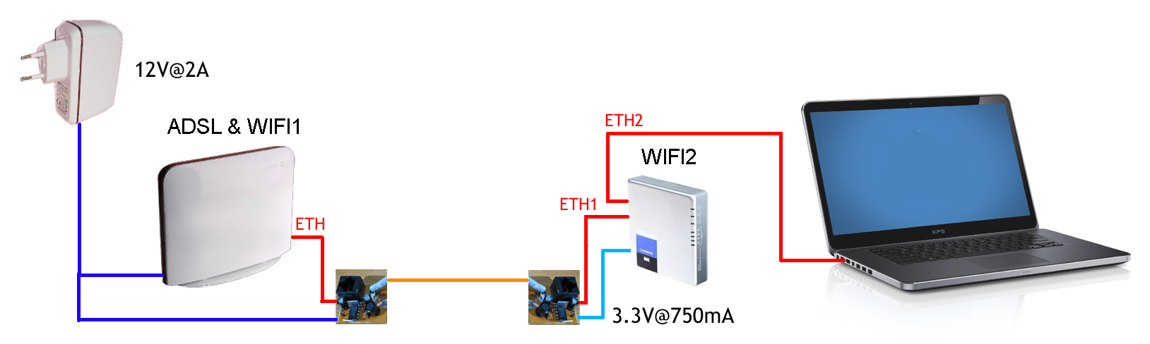
I got the DC-DC converter from a cheap car adaptor for mobile phones, it uses a fairly common MC34063A chip, you can find some online tools to get the correct values of the components to get the desired output voltage. As input voltage I used the same adaptor of the ADSL router, cutting the cable and soldering the circuit to it. Next you can find the values I used to convert from 12V to the 3.3V@750mA and also the resulting circuits I designed.


![]()
To make the circuits I used the technique of printing them with a laser printer and transferring the tonner to the PCB with a laminator, you can find more information about this method on Internet.

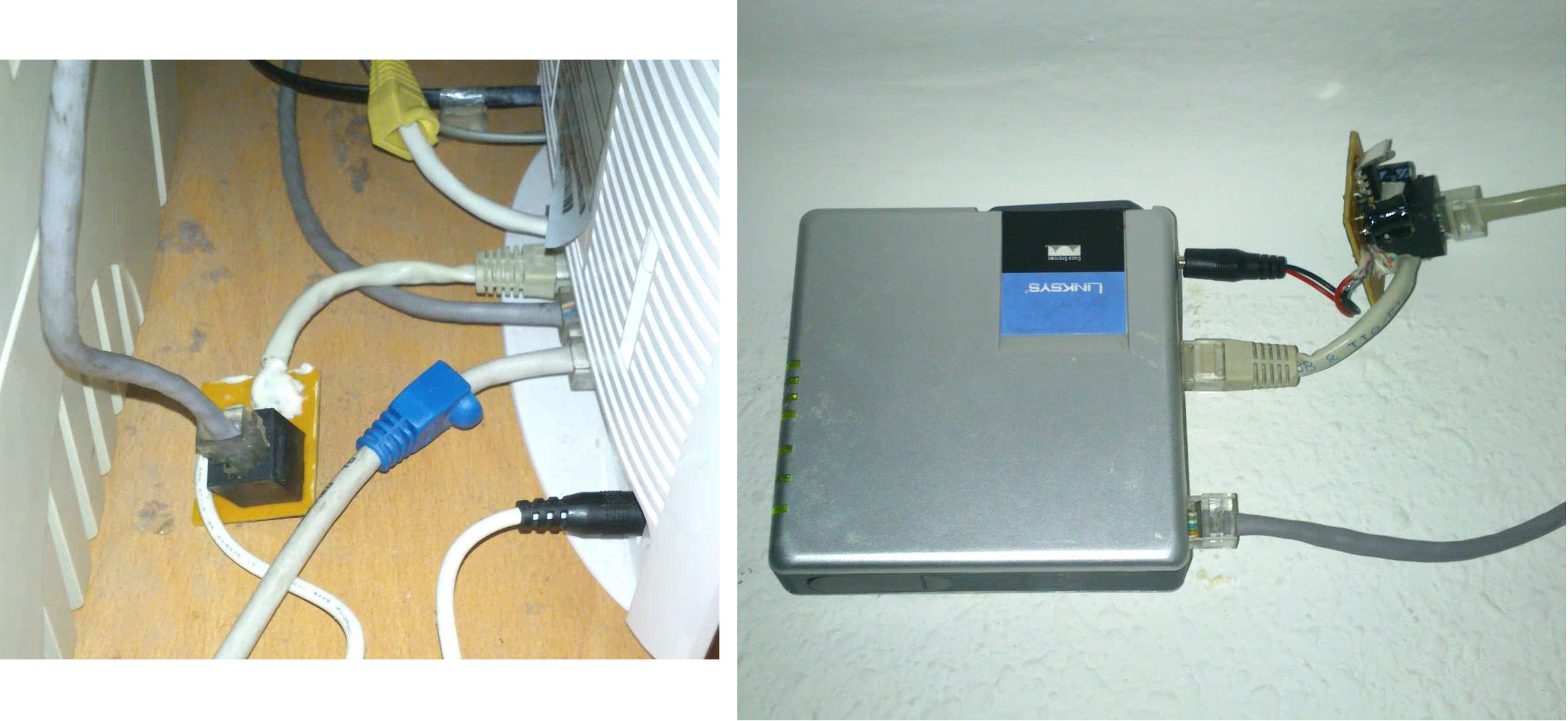
These are pictures of the final DC-DC converter, I placed a little aluminium plate with thermal paste below the chip to dissipate the heat as it gets quite hot.

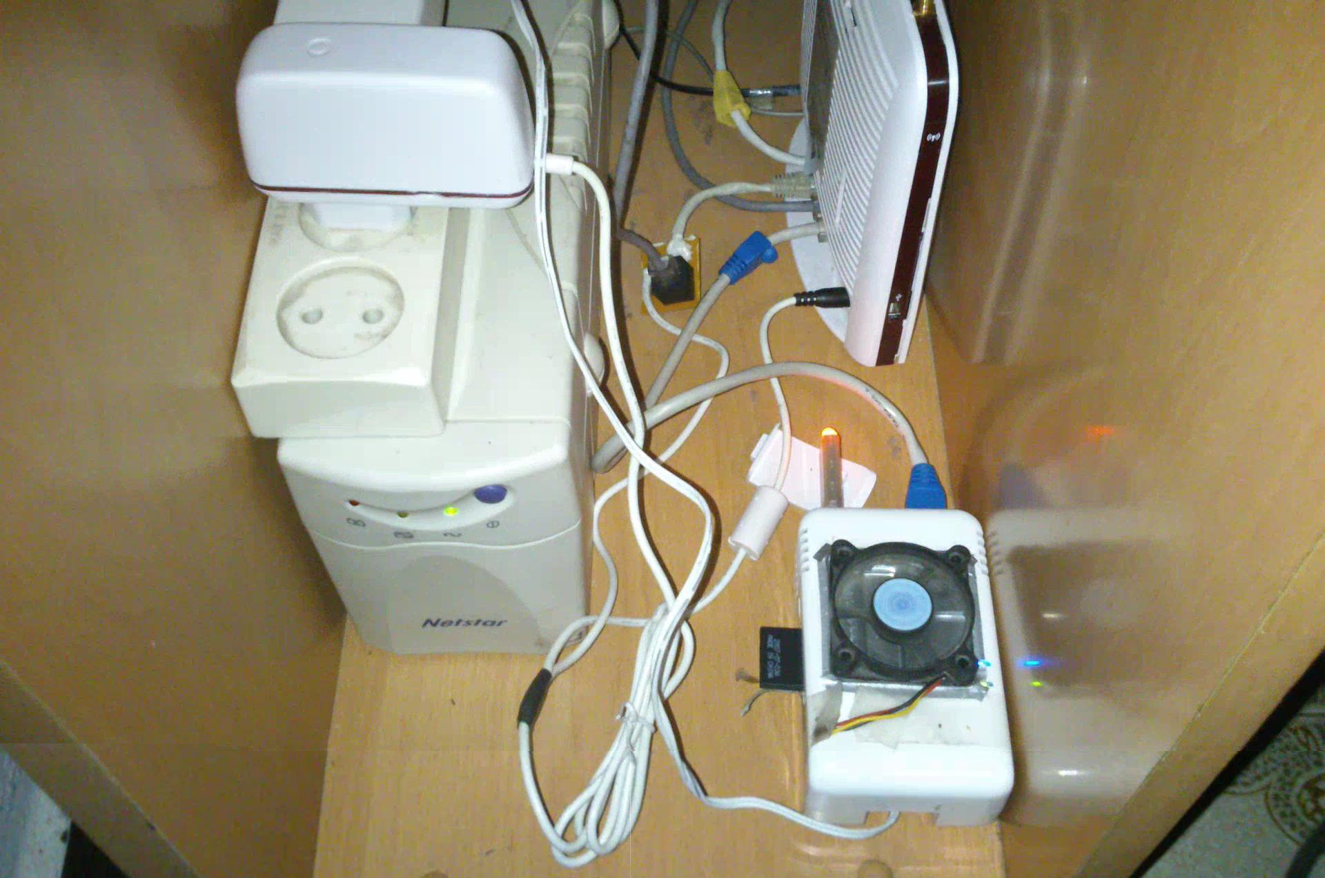
To conclude, these are the photos of both circuits in place and working. You can also see a SAI to avoid losing Internet in case of power outage and my Sheevaplug computer where this web is hosted.